Back to Course List
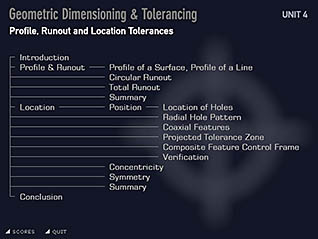
GD&T: Profile, Runout and Location Tolerances
- Product ID
- artsgdt4
- Training Time ?
- 45 to 90 minutes
- Language(s)
- English
- Video Format
- Standard Definition
- Required Plugins
- MasteryNet Player
- Lesson Interactions
- 43
- Quiz Questions
- 26
Overview
This is the last of a four part training series for Geometric Dimensioning & Tolerancing, which builds the ability to read and interpret GD&T symbols. Understanding the international engineering language of Geometric Dimensioning & Tolerancing is essential for communicating in the global marketplace.
This course focuses on profile tolerances and runout tolerances; position concentricity, and symmetry.
![]() This course is in the Advantage™ format, to read about Advantage™ features click here.
This course is in the Advantage™ format, to read about Advantage™ features click here.

- Rich multimedia presentation with interactions and quiz
- Print certificate and wallet card
- You have 30 days to complete the course
Audience
Anyone who needs to understand the international engineering language of Geometric Dimensions and Tolerancing.
Topics
The course presents the following topical areas:
- Profile of a Surface, Profile of a Line
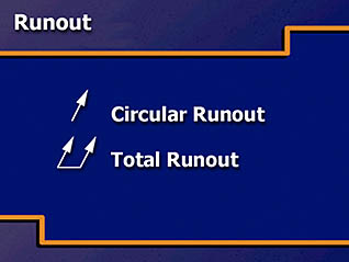
- Circular Runout
- Total Runout
- Summary
- Location of Holes
- Radial Hole Pattern
- Coaxial Features
- Projected Tolerance Zone
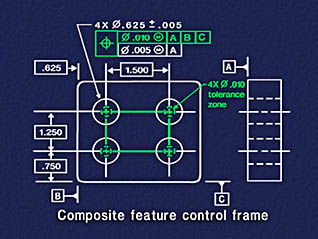
- Composite Feature Control Frame
- Verification
- Concentricity
- Symmetry
- Summary
Intended Performance Outcomes
Upon successful completion of this course you will be better prepared to:
- Use and interpret the profile of a surface or line.
- Use circular runout to control part surface.
- Know when total runout is used within a part drawing.
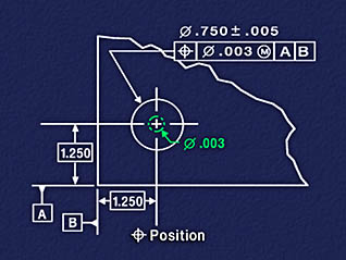
- Identify and interpret position tolerances for holes on a part drawing.
- Calculate the virtual condition of a coaxial feature.
- Identify when a projected tolerance zone is used.
- Identify when a composite feature control frame is used on a drawing.
- Identify and interpret when a concentricity tolerance is used on a drawing.
- Identify and interpret when a symmetry tolerance is used on a drawing.
© Mastery Technologies, Inc.
