Transformer Banks 4: Voltage Phasor Diagrams
- Product ID
- tbphsmpg
- Training Time ?
- 72 to 144 minutes
- Language(s)
- English
- Video Format
- Standard Definition
- Required Plugins
- MasteryNet Player
- Lesson Interactions
- 48
- Quiz Questions
- 32
This training is the fourth training in the "Transformer Bank Workshop" series. All the courses in this series use full-screen, full-motion video.
It’s difficult to arrange for power outages to service power distribution systems. Your line personnel will be in situations where they have to parallel two transformer banks to transfer load from one bank to the other; avoiding an outage. To parallel banks, line personnel must be able to determine angular displacement and other facts about the bank. They can’t guess! A solid grasp of voltage phasor diagrams will help your workers understand exactly how a bank is connected, or should be connected.
This "near hands-on" training will teach your workers how to form voltage phasor diagrams for the delta and the wye. They will combine their diagrams to represent transformations. They will also use phasor diagrams to document an existing transformer bank and to build a bank. And finally they will learn the rules for paralleling two transformer banks and how to test their connections.
The training uses clear and concise presentations, interactions, and 3D animations to actively involve your workers in the instruction and to clarify sometimes difficult concepts.
This training was produced in collaboration with Otter Tail Power Company and Gordon Solee, PE. The program is based on Mr. Solee’s popular and respected "Transformer Hands-On Workshop".
![]() This course is in the Advantage™ format, to read about Advantage™ features click here.
This course is in the Advantage™ format, to read about Advantage™ features click here.
- Install on any SCORM LMS
- Rich multimedia presentation with interactions and quiz
- Print certificate and wallet card
- You have 30 days to complete the course
Electrical distribution line personnel, engineers, and line supervisors.
- The Diagram
- Representing Connections
- Diagramming A Bank
- Building A Bank
- Parallel Banks
-
Draw phasor diagrams for common connections.
- Draw a phasor diagram for a delta connection.
- Draw a phasor diagram for a wye connection.
-
Draw a phasor diagram for a proposed bank.
- Draw a voltage phasor diagram for a delta-delta bank with 0 degrees angular displacement.
- Draw a voltage phasor diagram for a delta-wye bank with 30 degrees angular displacement.
- Draw a voltage phasor diagram for a wye-wye bank with 180 degrees angular displacement.
- Draw a voltage phasor diagram for a wye-delta bank with 210 degrees angular displacement.
-
Draw a voltage phasor diagram for an existing bank
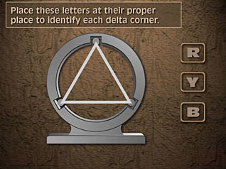
- Identify a hight side connection as a delta or a wye.
- Identify the R-Y-B phasors on a high side diagram.
- Identify the three phasors by number according to transformer position for a high side diagram.
- Place the arrow heads on the high side diagram.
- Position the H1 bushing on the high side diagram.
- Position the H2 bushing on the high side diagram.
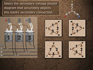
- Given the three voltage phasors, identify the X1 end point on the secondary diagram.
- Given the three voltage phasors, identify the X3 end point on the secondary diagram.
- Identify the secondary phase connections on the phasors.
- Postion the second voltage phasor in proper relationship to the first on the secondary diagram.
-
Construct a bank from a voltage phasor diagram.
- Connect the hight side from a wye diagram, H1 to source.
- Connect the hight side from a wye diagram, H2 to source.
- Connect the hight side from a delta diagram, H1 to source.
- Connect the hight side from a delta diagram, H2 to souce.
- Connect the hight side from an open wye diagram.
- Connect the hight side from an open delta diagram.
-
Define requirements to parallel two banks.
- Identify same angular displacement on both banks as a requirement.
- Identify same voltage ratio on both banks as a requirement.
- Identify same sequence on both banks as a requiremnt.
- Identify the lighting transfromer connected to the same phase on both banks as a requirement.
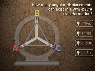
- Cite the need to consider the angular displacement.
-
Construct a bank for specific angular displacement.
- With a given delta high side, connect a bank for 180 degree angular displacement, 120 or 240 volt, three-phase, four-wire.
- With a given wye high side, connect a bank for 210 degree angular displacement, 120 or 240 volt, three-phase, four-wire.
- With a given wye high side, connect a bank for 30 degree angular displacement, 120 or 240 volt, three-phase, four-wire.
- With a given wye high side, connect a bank for zero degree angular displacement, 120 or 208 volt, three-phase, four-wire.
© Mastery Technologies, Inc.
